Boiler Specifications
Steam generation rate and operating pressure
Engineering Report
Generate a printable PDF report with all inputs, equations, and results
Boiler Feed Pump Sizing, TDH Formulas & Feed Tank Engineering
Industrial boiler feed pump calculation is a critical discipline uniting multi-phase thermodynamics, high-pressure rotodynamic machinery, and transient piping acoustics. This comprehensive engineering guide by Zolvia explores governing mathematical formulations, IAPWS-IF97 fluid properties, deaerator storage tank sizing, and cavitation safety margins per ASME BPVC Section I and API 610.
Dynamic Mass & Volume Sizing
Seamlessly computes continuous blowdown equilibrium, water thermal expansion curves using IAPWS-IF97 standards, and ASME flow safety allowances.
Deaerator & Feed Tank Retention
Determines effective storage volumes using the 10–20 minute MCR rule, static elevation heads, and NPSH margins under saturated temperature conditions.
API 610 Machinery Standards
Recommends optimal pump casing configurations (OH2 vs BB3 vs BB5) and generates verifiable, stamped PDF engineering datasheets for EPC procurement.
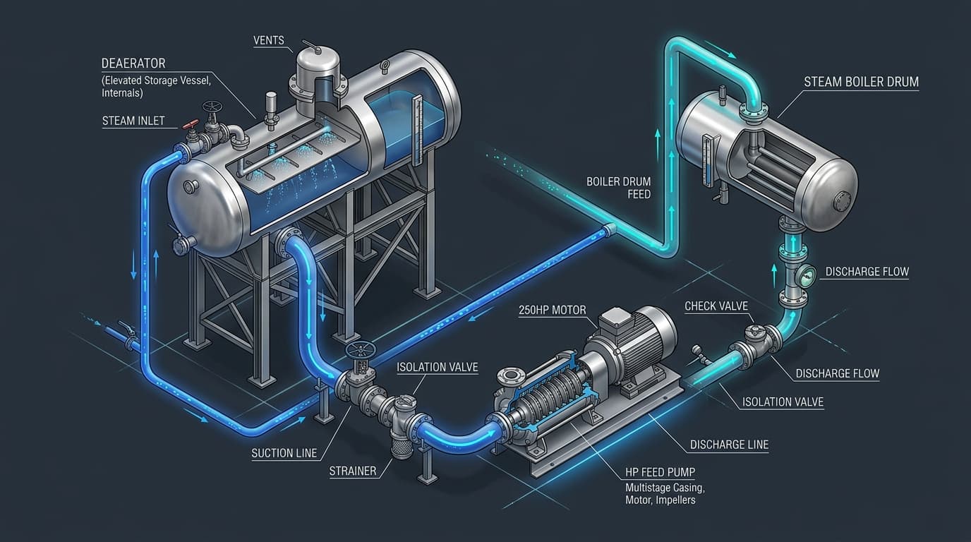
Figure 1: High-Pressure Multistage Centrifugal Boiler Feed Pump Circuit with Elevated Deaerator Tank, Economizer Loop, and Minimum Flow Recirculation Line.
Governing Mathematical Formulations & Hydraulic Derivations
In industrial steam generation facilities, boiler feed pumps (BFPs) operate as the continuous thermodynamic lifeline of the Rankine power cycle. Sizing these critical machines requires simultaneous resolution of mass conservation, non-linear fluid thermophysical properties, and rotational mechanical limits:
1. Mass & Volumetric Flow Formulation
Q_operating = M_feed / ρ_water(T, P)
Q_design = Q_operating × S_flow (1.15 to 1.25)
Feedwater flow must compensate for continuous surface blowdown (X_blowdown) required to control total dissolved solids (TDS), plus an ASME Section I mandated 15% to 25% surge margin for rapid load pickups.
2. Total Dynamic Head (TDH) Equation
H_discharge = [ (P_drum × 1.05 + ΔP_losses) / (ρ × g) ] + Z_drum
H_suction = [ P_deaerator / (ρ × g) ] + Z_tank - h_f_suction
The discharge head must overcome boiler operating drum pressure with a 5% overpressure cushion (safety valve reseat margin), economizer friction losses (1.5–3.5 bar), modulating feed valve drops (2–4 bar), and vertical elevation rise.
3. Hydraulic & Brake Horsepower (BHP)
P_brake = P_hydraulic / η_pump
P_motor = P_brake × S_motor (1.10 to 1.15)
Shaft power depends directly on pump efficiency (η_pump), which typically ranges between 68% and 82% for multistage centrifugal geometries. Motor nameplate capacity includes NEMA / IEC non-overloading margins.
4. Net Positive Suction Head (NPSHa)
In Saturated Deaerators: P_suction = P_vapor
∴ NPSHa = Z_static_liquid - h_f_suction - h_losses
Under deaerator saturation conditions, vapor pressure equals vessel pressure. Thus, net suction margin is generated solely by the physical liquid static column above the pump centerline minus line friction and suction strainer resistance.
Boiler Feed Tank Sizing & Deaerator Storage Volume Rules
A boiler feed tank or deaerator storage vessel serves two indispensable roles: removing non-condensable corrosive gases (dissolved O₂ and CO₂) and acting as a critical hydraulic surge buffer between returning steam condensate, fresh treated makeup water, and boiler feedwater injection pumps.
The 10 to 20 Minute Retention Criterion: Industrial boiler engineering standards established by ASME, the Hydraulic Institute, and Spirax Sarco recommend providing between 10 and 20 minutes of effective water volume calculated at the boiler’s Maximum Continuous Rating (MCR). Package firetube boilers operating on steady loads can operate reliably with a 10–12 minute reserve, whereas rapid-cycling industrial watertube boilers, biomass units, and power utility boilers require 15 to 20 minutes.
Total Shell Volume Expansion: The effective volume represents the usable liquid buffer between the low water level alarm and the high water overflow weir. Total internal vessel volume is calculated as:
This ensures 20% residual liquid capacity below the low alarm to maintain continuous pump submergence and 20% top vapor/disengagement space for deaeration steam distribution.
API 610 Boiler Feed Pump Classification & Architecture Selection
Selecting the appropriate mechanical architecture depends on drum pressure, feedwater temperature, and operational cycling severity. The table below outlines standard industrial pump categories:
| API 610 Type | Mechanical Configuration | Max Pressure Rating | Typical Boiler Application |
|---|---|---|---|
| API 610 OH2 | Single-Stage Overhung End-Suction, Centerline Mounted | Up to 25 bar (360 psi) | Low-pressure industrial package boilers & auxiliary condensate return loops |
| Vertical Inline (e.g. CR) | Vertical Multistage Ring-Section Centrifugal | Up to 35 bar (500 psi) | Commercial heating plants, small firetube steam generators (up to 15 t/h) |
| API 610 BB3 | Axially Split Multistage Between-Bearings, Opposed Impellers | Up to 120 bar (1,740 psi) | Medium-pressure watertube boilers, cogeneration plants, and chemical refineries |
| API 610 BB5 | Double-Casing Radially Split Barrel Multistage | Up to 300+ bar (4,350 psi) | Supercritical thermal power stations, CCGT steam generators, and severe cycling |
Feed Pump Sizing Matrix: Industrial Steam Capacities
Reference sizing metrics for standard industrial boilers operating with feedwater at 105°C (221°F), continuous blowdown of 4%, and a 15% ASME flow allowance:
| Boiler Rating | Steam Evaporation | Design Flow Rate (m³/h) | Design Flow Rate (GPM) | Typical TDH Range (m) |
|---|---|---|---|---|
| 50 BHP Package | 1,725 lb/h (782 kg/h) | 0.97 m³/h | 4.28 GPM | 110 – 140 m |
| 200 BHP Package | 6,900 lb/h (3,130 kg/h) | 3.88 m³/h | 17.1 GPM | 130 – 170 m |
| 10 Ton/hr Watertube | 22,046 lb/h (10,000 kg/h) | 12.39 m³/h | 54.5 GPM | 220 – 380 m |
| 30 Ton/hr Industrial | 66,138 lb/h (30,000 kg/h) | 37.16 m³/h | 163.6 GPM | 450 – 650 m |
| 80 Ton/hr Utility CHP | 176,370 lb/h (80,000 kg/h) | 99.10 m³/h | 436.3 GPM | 800 – 1,200 m |
Frequently Asked Questions (FAQ)
Deep Dive into Cavitation & Piping Diagnostics
Explore our troubleshooting guides on acoustic vibration signatures, minimum flow recirculation systems, and NPSH margins.