Boiler Feed Pump Calculation: The Definitive Hydraulic Sizing Guide
Executive Engineering Summary
Boiler feed pumps (BFPs) operate under severe thermodynamic boundary conditions: high static discharge heads (up to 300 bar in supercritical cycles), near-saturation suction temperatures (105°C to 180°C), and steep transient thermal gradients. Incorrect hydraulic sizing leads to either premature impeller destruction through cavitation shockwaves or severe power wastage through excessive throttle valve dissipation. This whitepaper establishes deterministic equations, IAPWS-IF97 fluid density models, and practical design benchmarks for consulting engineers.
01.Mass Balance & Volumetric Flow Formulation
In steady-state steam boiler operation, mass entering the steam drum must balance steam generation, continuous surface blowdown, and intermittent bottom sludge purge. The mass flow requirement is formulated as:
Where:
- M_steam: Maximum Continuous Rating (MCR) steam production (kg/h).
- X_blowdown: Continuous surface blowdown fraction, normally 3% to 6% in industrial watertube boilers to maintain boiler water silica and electrical conductivity limits.
The Critical Role of Temperature in Fluid Density
A frequent design error in preliminary sizing is assuming ambient water density (1,000 kg/m³ or 8.34 lb/gal). In modern thermal systems, feedwater is preheated in deaerators to prevent thermal shock and remove dissolved oxygen:
| Feedwater Temp (°C) | Saturation Pressure (bar a) | IAPWS Density ρ (kg/m³) | Volumetric Expansion Factor |
|---|---|---|---|
| 20°C (Ambient) | 0.023 bar | 998.2 kg/m³ | 1.000 (Baseline) |
| 105°C (Atmospheric Deaerator) | 1.208 bar | 954.7 kg/m³ | +4.55% Volume |
| 130°C (Pressurized Deaerator) | 2.701 bar | 934.8 kg/m³ | +6.78% Volume |
| 160°C (High-Pressure Deaerator) | 6.181 bar | 907.3 kg/m³ | +10.02% Volume |
Therefore, operating volumetric flow rate must be computed via:
To satisfy ASME BPVC Section I (PG-61) and EN 12952-7 guidelines, a design safety factor (S_flow) between 1.15 and 1.25 is applied:
02.Total Dynamic Head (TDH) Mathematical Breakdown
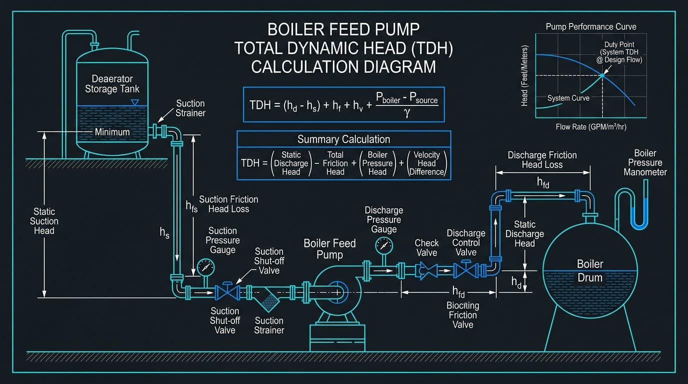
Total Dynamic Head represents the net mechanical energy per unit weight that the pump impellers must impart to the fluid. By applying the steady-flow energy equation (Bernoulli equation) between the deaerator liquid surface (point 1) and the steam drum internal sparger (point 2):
Expanding both terms reveals the discrete hydraulic components:
Discharge Head Components (H_discharge):
- Drum Design Pressure Head: (P_drum × 1.05) / (ρ × g) to account for safety valve lift pressure.
- Economizer Pressure Drop: High-velocity finned tubes introduce 1.5 to 3.5 bar (15–35 m) of friction loss.
- Feedwater Regulating Valve (FRV) Drop: For proper flow controllability, FRVs require a minimum pressure drop of 2.0 to 4.0 bar (20–40 m) or 20% of total system friction at full load.
- Discharge Line Friction: Darcy-Weisbach losses across pipe runs, check valves, isolating gate valves, and flow meters.
- Static Elevation: Height difference between pump centerline and boiler drum water level (Z_discharge).
Suction Head Components (H_suction):
- Deaerator Vessel Pressure Head: P_deaerator / (ρ × g).
- Static Suction Elevation: Positive vertical height of the deaerator liquid level above the pump centerline (+Z_suction).
- Suction Line Friction: Line losses across suction strainers, vortex breakers, and suction block valves (-h_f_suction).
03.Cavitation Physics & Net Positive Suction Head (NPSHa)
Cavitation is the most destructive operational hazard in boiler feed pumping. When static local pressure inside the first-stage impeller eye falls below the fluid’s saturation vapor pressure, microscopic vapor bubbles form instantaneously. As these bubbles sweep into regions of higher pressure along the impeller vane, they implode violently with localized shockwave pressures exceeding 1,000 MPa (150,000 psi), eroding hardened stainless steel impellers within weeks.
Hydraulic Institute NPSH Margin Guidelines (ANSI/HI 9.6.1)
To guarantee long-term impeller mechanical integrity, the Hydraulic Institute mandates a minimum safety margin ratio:
| Service Category | Operating Temperature | Recommended Margin Ratio (NPSHa / NPSHr) | Absolute Head Margin |
|---|---|---|---|
| General Industrial Feedwater | 100°C – 120°C | 1.3 to 1.5 × NPSHr | Min +1.5 m (+5.0 ft) |
| High-Pressure Watertube Boilers | 120°C – 150°C | 1.5 to 1.8 × NPSHr | Min +2.5 m (+8.2 ft) |
| Supercritical Utility Plants | > 150°C | 2.0+ × NPSHr | Min +4.0 m (+13.1 ft) |
04.Brake Horsepower (BHP) & Motor Sizing Rules
Hydraulic power represents the theoretical energy transferred to the liquid column, while Brake Horsepower (BHP) accounts for mechanical seal friction, disc friction, and impeller hydraulic inefficiencies:
P_brake = P_hydraulic / η_pump [kW]
For US Customary Units:
API 610 Electric Motor Margin Guidelines
To prevent motor breaker trips during transient startup, cold water testing (where water density is higher), or end-of-curve operation, API 610 Table 11 establishes mandatory motor nameplate margins:
- Motor Rating < 22 kW (< 30 HP): Minimum 125% of maximum shaft brake power.
- Motor Rating 22 kW to 55 kW (30 to 75 HP): Minimum 115% of maximum shaft brake power.
- Motor Rating > 55 kW (> 75 HP): Minimum 110% of maximum shaft brake power.
05.Step-by-Step Industrial Numerical Case Study
Plant Design Parameters:
- Boiler Capacity: 25,000 kg/h (25 ton/hr) steam
- Operating Drum Pressure: 40.0 bar gauge (41.0 bar abs)
- Deaerator Pressure: 1.5 bar gauge (2.5 bar abs)
- Deaerator Temperature: 127.4°C (Saturation)
- Continuous Blowdown: 4.0%
- Flow Safety Margin: 15% (S_flow = 1.15)
- Static Elevations: Drum = +12.0 m, Deaerator = +7.5 m
- Piping Friction: Discharge = 2.8 bar, Suction = 0.15 bar
- Pump Efficiency (η): 74.0%
Step 1: Compute Mass & Volumetric Flow
ρ(127.4°C, 2.5 bar) = 937.2 kg/m³
Q_operating = 26,000 / 937.2 = 27.74 m³/h
Q_design = 27.74 × 1.15 = 31.90 m³/h (140.5 GPM)
Step 2: Total Dynamic Head (TDH)
ΔP_static = (42.0 - 1.5) = 40.5 bar
ΔP_friction = 2.8 + 0.15 = 2.95 bar
ΔP_total = 40.5 + 2.95 = 43.45 bar = 4,345,000 Pa
Pressure Head = 4,345,000 / (937.2 × 9.80665) = 472.78 m
Static Head = 12.0 - 7.5 = +4.5 m
TDH = 472.78 + 4.5 = 477.28 meters (1,565.9 ft)
Step 3: Shaft Brake Horsepower & Motor Rating
P_brake = 38.83 / 0.74 = 52.47 kW (70.36 BHP)
Applying API 610 Motor Margin (115% for 22–55 kW):
P_motor_req = 52.47 × 1.15 = 60.34 kW
Standard IEC Motor Selected: 75 kW (100 HP, 2-pole, 2950 RPM)
Step 4: NPSHa Verification
h_f_suction = 0.15 bar × 100,000 / (937.2 × 9.80665) = 1.63 m
NPSHa = 7.50 - 1.63 = 5.87 meters (19.26 ft)
Manufacturer NPSHr = 3.20 m
Safety Ratio = 5.87 / 3.20 = 1.83 (PASS > 1.50)
06.Boiler Feed Tank Sizing & Geometry Design Rules
Boiler feed tanks and deaerator storage vessels must provide sufficient liquid hold-up volume to decouple steam demand variations from raw makeup water treatment plants.
10–12 Minute Retention:
Standard for base-loaded packaged firetube boilers with reliable city water supply and continuous automated makeup level valves.
15–20 Minute Retention:
Mandatory for power generation boilers, industrial pulp and paper facilities, chemical batch reactors, and systems with intermittent batch condensate returns.
To account for low-level trip switches (20% residual) and upper deaeration spray clearance (20% vapor disengagement space), total vessel geometry is sized using V_gross = V_usable / 0.60.
Run Your Custom Boiler Feed Pump Calculation Now
Test your exact boiler operating pressure, steam output, deaerator elevation, and piping losses on our interactive 3D engineering platform.
Frequently Asked Technical Questions
How does continuous boiler blowdown alter pump flow sizing?
Boilers require continuous surface blowdown (typically 2% to 7% of steaming rate depending on makeup water silica and conductivity limits) to prevent TDS scaling on heat-transfer surfaces. The pump mass flow must satisfy M_feed = M_steam × [1 + (X_blowdown / 100)], ensuring steady drum water level is maintained during full blowdown rates.
Why does assuming water density of 1,000 kg/m³ create dangerous undersizing?
Feedwater drawn from pressurized deaerators is hot, typically 105°C to 160°C. Under these conditions, thermal expansion lowers water density to ~910–955 kg/m³. If an engineer assumes 1,000 kg/m³, the calculated volumetric displacement (m³/h or GPM) will be underestimated by 5% to 10%, causing the pump to run off-curve at end-of-curve flow where motor overload and cavitation occur.
What is the standard ASME safety margin for boiler feed pump discharge pressure?
Per ASME Boiler and Pressure Vessel Code (BPVC) Section I, the boiler feed pump must supply feedwater at a pressure sufficient to overcome the highest safety valve setpoint plus full piping friction, economizer drop, and feed regulating valve drop. A minimum 5% to 10% head margin above drum operating pressure is standard practice to prevent backflow during transient steam demand spikes.
Why does deaerator saturation eliminate pressure head in NPSHa calculations?
Because the deaerator vessel operates at boiling equilibrium where the liquid surface pressure is equal to the liquid saturation vapor pressure (P_suction = P_vapor), the term (P_suction - P_vapor) / (ρ × g) equals zero. The net positive suction head available is therefore purely dependent on the static vertical liquid elevation above the pump impeller centerline minus suction friction losses.
What is Minimum Continuous Stable Flow (MCSF) and why is an Automatic Recirculation Valve (ARV) required?
At low boiler steam demand (such as plant startup or hot standby), a feed pump operating near shutoff head dissipates mechanical shaft energy into fluid heat. Within seconds, fluid temperature exceeds saturation temperature, causing explosive internal vaporization and bearing seizure. An ARV automatically bypasses a minimum stable flow (typically 20% to 35% of BEP flow) back to the deaerator.