Boiler Feed Tank Sizing Guide: Retention Time, Storage Volume & Static Elevation
Engineering Design Overview
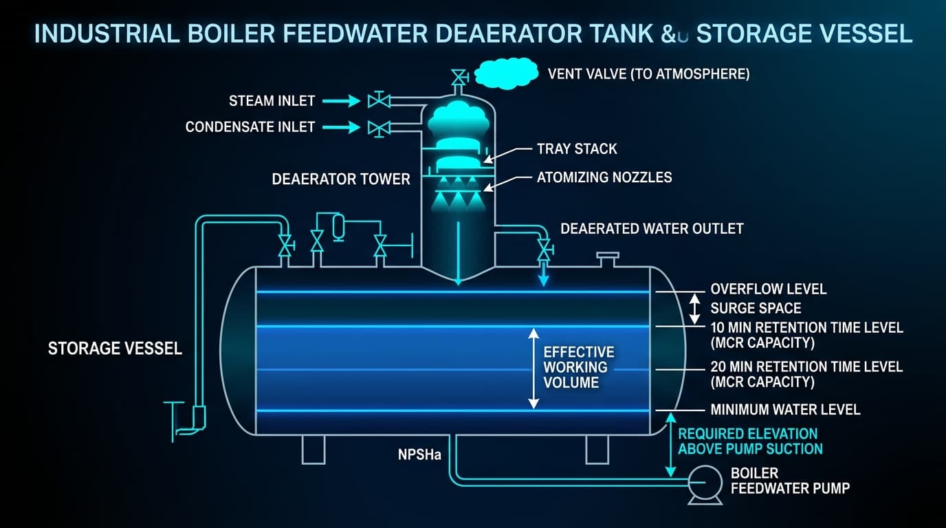
The boiler feed tank (also termed the feedwater hotwell or deaerator storage vessel) is the primary hydraulic and thermal reservoir of any steam plant. Sizing a feed tank requires balancing three physical engineering constraints: (1) providing an adequate liquid buffer to survive sudden water treatment interruptions, (2) absorbing condensate surge returns without atmospheric venting loss, and (3) elevating the vessel sufficiently above pump suction to eliminate flashing cavitation.
01.Effective Water Retention Time Formulations
Retention time dictates the minutes of uninterrupted steam output a boiler can deliver if cold treated makeup water flow stops completely. The required effective storage volume (V_effective) is calculated as:
Where:
- M_steam: Boiler steam generation capacity at Maximum Continuous Rating (kg/h).
- X_blowdown: Continuous surface blowdown rate (typically 3%–5%).
- ρ_water(T): Saturated water density calculated at storage temperature via IAPWS-IF97 (kg/m³).
- t_retention: Design retention duration in minutes.
Recommended Retention Durations by Boiler Class
| Plant Service Type | Recommended Retention Time | Design Rationale |
|---|---|---|
| Packaged Firetube Boilers | 10 to 12 Minutes | Large internal water volume acts as an inherent buffer against short-term feed delays. |
| Industrial Watertube Boilers | 15 to 20 Minutes | Smaller drum volumes; water level will deplete rapidly under sudden steam draw. |
| Biomass & Waste-to-Energy | 20 to 30 Minutes | Combustion cannot be stopped instantly; feed water must continue during emergency trip cooling. |
| Combined Cycle / Utility Power | 15 to 20 Minutes | Mandated by EPRI and ASME to permit orderly turbine load runback without dry-out. |
02.Gross Tank Volume & Shell Geometric Proportions
In real-world vessel fabrication, only 60% of a horizontal cylindrical shell represents the active operating buffer. The remainder is divided into three distinct operational zones:
1. Unusable Bottom Heel (Lower 20%):
The liquid below the Low-Low Level Trip switch prevents vortexing into the pump suction nozzle and accommodates sludge settlement.
2. Active Effective Buffer (Middle 60%):
The working liquid swing between normal liquid level (NLL), makeup valve opening trigger, and high-level alarms.
3. Upper Vapor / Disengagement Space (Top 20%):
Space above high-level overflow to disengage flash steam, accept sudden batch condensate slugs, and permit steam spray distribution.
For standard horizontal cylindrical deaerator storage tanks with 2:1 semi-ellipsoidal heads, the recommended length-to-diameter ratio is:
This ratio optimizes structural saddle support spacing while maintaining sufficient horizontal liquid surface area for smooth deaeration.
03.Tank Elevation Physics: The NPSHa Foundation
Because deaerators strip dissolved gases using steam, the water is at its boiling point (saturation pressure equals vessel operating pressure). Under saturation:
Where:
- Z_suction: Vertical height from the feed pump centerline to the deaerator Low-Low Water Level (m).
- h_f_suction: Total suction piping friction loss at design flow (m).
- h_strainer: Allowance for 50% clogged suction strainer (typically 0.3 to 0.8 m).
Recommended Deaerator Elevation Guidelines
| Feed Pump Speed / Type | Typical NPSHr Range | Recommended Tank Elevation (Z_suction) |
|---|---|---|
| Low-Speed (1,450 RPM / 4-pole) | 1.5 to 2.5 meters | 4.0 to 5.5 meters (13 to 18 ft) |
| High-Speed (2,950 RPM / 2-pole) | 3.0 to 5.0 meters | 6.5 to 9.0 meters (21 to 30 ft) |
| VFD Controlled Multistage | 3.5 to 6.0 meters | 7.5 to 11.0 meters (25 to 36 ft) |
04.Worked Engineering Sizing Example
Design Input Specifications:
- Boiler Capacity: 40,000 kg/h (40 t/h steam)
- Deaerator Temperature: 105.0°C (Atmospheric deaeration)
- Continuous Blowdown: 5.0%
- Retention Time Target: 15 minutes
- Water Density (105°C): 954.7 kg/m³
- Pump NPSHr: 3.8 meters
- Suction Pipe Losses: 0.6 meters (piping + strainer)
Step 1: Compute Mass Flow
Step 2: Effective Retention Volume
Step 3: Gross Tank Shell Volume
Step 4: Minimum Tank Elevation for Cavitation Protection
Z_suction_min = NPSHa_required + h_f_suction = 5.70 + 0.60 = 6.30 meters (20.7 ft)
Calculate Your System's Exact Tank & Pump Hydraulics
Simulate feed tank suction elevations, suction line friction, and pump NPSHa margins dynamically on the Zolvia platform.
Frequently Asked Questions: Boiler Feed Tanks
What retention time is standard for industrial boiler feed tanks?
The industry benchmark is 10 to 20 minutes of effective water volume calculated at the boiler Maximum Continuous Rating (MCR). Packaged firetube boilers operating with steady steam demand can utilize 10–12 minutes. Watertube boilers, cogeneration plants, and paper mills experiencing volatile batch demands require 15 to 20 minutes.
How does boiler feed tank elevation prevent cavitation in boiler feed pumps?
In a thermal deaerator or hot atmospheric feed tank, feedwater exists near its boiling point (100°C–130°C). Suction pressure equals the liquid vapor pressure. To prevent boiling inside the pump suction impeller, static elevation (Z_suction) must provide sufficient positive head to exceed the manufacturer NPSH required (NPSHr) plus suction friction losses.
What is the difference between effective volume and gross tank volume?
Effective volume is the usable liquid buffer between the low water level alarm (or trip switch) and the high water overflow weir. Gross volume is the total geometric volume of the cylindrical shell. Typically, Gross Volume = Effective Volume / 0.60 to account for the 20% unusable bottom liquid heel and 20% top vapor disengagement zone.
Why should a boiler feed tank have a steam sparging preheating system?
Preheating feedwater in the feed tank to at least 85°C–90°C (atmospheric) or 105°C (pressurized deaerator) drives off dissolved oxygen and free carbon dioxide. This prevents severe pitting corrosion in carbon steel economizer tubes and boiler drums without requiring excessive chemical scavenger dosing.